
It was told that it is impossible to connect standard controller-less LCD screen to the computer’s printer port. The main reason it is not working is the speed of the computer. In fact, the speed of printer port.
I decided to test this situation and attached Sharp LM64P10 (640 x 480 STN) screen to my computer. And here is the result:
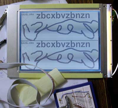
The image is repeating because the first 4 bits of the data byte is for upper screen and other bit are for lower part. As I was missing spare pins on my LPT to “breadboard” adapter, I just connected the lower nibble with upper.
The refresh rate of the screen is horrible. The only reason you see this nice image, is that digital photo camera is using very long exposure (half of the second). The real refresh rate is only 2…3 fps. The manufacturer recommends to use at least 80 fps. 🙂

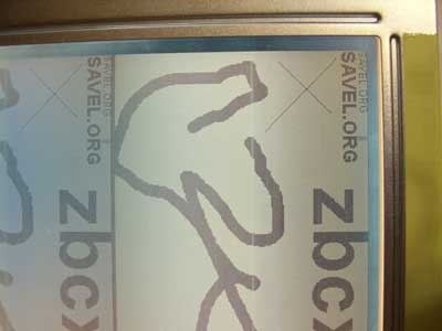
The data is going to the right place- pixel to pixel. Now I need to attach some SED or Hitachi controller or build some self-made controller based on FPGA.
Technical stuff below…
There are lots old LCD screens without controller. This particular screen is removed from some ancient laptop. The screen is dynamic and need to be refreshed at least 60 times per second. If you stop pumping data to the screen and turn off the clock signal the LCD will stop and the screen will erode. Of don’t forget to turn off the Vee power. The main symptom that LCD is stalled is when you see some yellow color on the screen.
In real life all this refresh job is done by special LCD controller with video RAM. In my experiments all controller job is done by computer. I was using MS Visual Basic 6 to drive the screen.
Computer is fast enough to do the job, but the printer port is very slow. So this design is impractical.
The pin-out is very simple and almost identical in all screens. There are three sync signals: HSYNC (CP1), VSYNC (S) and Pixel Clock (CP2). In brackets are Sharp names. The data is fed by 8 lines, 4 bits for upper side of the screen and four for lower. So the screen is filled in twice the VSYNC speed. In new screens data are for the whole screen.
Description of this screen:
1. S- Start-up signal (VSYNC), active H;
2. CP1- Input data latch (HSYNC), active H->L;
3. CP2- Data input clock, active H->L, (min 152nS);
4. DISP- Display control, ON=H, OFF=L, connect to +5V, Vdd to turn on;
5. Vdd- Logic power, 5V;
6. Vss- Ground, GND;
7. Vee- LCD power -15V typical (attention, negative voltage), max -25V;
8-11. DU0-DU3, Upper display data, H=ON, L=OFF;
12-15. DL0-DL3, Lower display data, same as above.
Recommended frame rate is 8…16 mS. So max speed is 125Hz, optimal-85Hz. In my case it is only 2…3Hz.
This small part of the program describes how the signals must be send to the screen:
While 1

WriteByte (VSYNC + HSYNC)

WriteByte (VSYNC)

For eil = 0 To 240

    j = eil * 160

    For i = 0 To 159

     duom = a(i + j)

        WriteByte (duom + CLOCK)

        WriteByte (duom)

    Next i

WriteByte (HSYNC)

Next eil

Wend
Attention, BASIC is SLOW. So nobody is taking care of the delays. In real world there must be some delays in signal. Delays are described in datasheet.
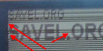
There is some bug in timing, so you can see 159 columns instead of 160. When using 160 sometimes some dark line appear in the screen. After I reduced to 159 the image is stable.
Hi. I find great this! I try turn on a Sharp LCD LM80c36, but almost complete lost. I found some little info about display, but no can get it working. Can you help-me to do some similar?
http://dinf.unicruz.edu.br/~hernandi/index.php?mostrar=noticiacompleta&id=0115230077
You site is great!
It seems to be standard VGA/SVGA screen with uncompressed video input. I didn’t understand your language, so I don’t know what is the problem. If you want to connect it to so standard computer video output, you need to find/buy video controller. In new devices there is only one chip and in very old ones there are MCU, DAC+pixel clock extractor, HV and VS separator. All this stuff is fed to LCD display using proper timing. I was trying to do something like this, but was stuck with proper timing problems. I think, that like in B/W monitor, there are some specific timing and sequence features. In this particular B/W monitor the critical part is timing of the beginning of the frame: I need to set HS and VS signal for some time, then remove HS keeping VS for a while. And it is very critical and not properly described in datasheet.
Can you post the compiled program, because i happen to own a LM32015, with the same pinout, only half the scan-lines(240) and i want to try to see if it’s working.After i will see it working, i will consider a solution for control(sed1335 board or perhaps an Atmega with external RAM).
Thank you, and this is a great article.
Here it is (source, some versions, some compiled stuff)…
LCD software.
I do not remember how it was working. My new computer do not have any printer port.